Saturday, 9 May 2015

Soil Constituents, Soil Properties & Types

Classification of soil

Types of soil (on the basis of moisture content)


  • Dry
  • Saturated
    A saturated soil is a two phase material consisting of a soil skeleton and voids which are saturated with water. It is reasonable to expect that the behavior of an element of such a material will be influenced not only by the forces applied to its surface but also by the water pressure of the fluid in the pores. Suppose that a soil sample having a uniform cross sectional area A is subjected to an applied load W, then it is found that the soil will deform. If however, the sample is loaded by increasing the height of water in the containing vessel, as shown in Fig lb, then no deformation occurs.

  • Partially saturated
    1. Types (on the basis of particle size)
      Gravel
      Sand
      Silt
      Clay
      Coarse
      Medium
      Fine
      Coarse
      Medium
      Fine
      Coarse
      Medium
      Fine
      Coarse
      Medium
      Fine
      60
      20
      6
      2
      0.6
      0.2
      0.06
      0.02
      0.006
      0.002
      0.0006
      0.0002
      Table 1. Particle Size Boundaries

      1. Coarse
      2. Fine
      3. Organic
      4. Gravel
      5. Sand
      6. Clay
      7. Silt
      8. Boulders
      9. Cobbles
      10. Peat


         Soil Properties

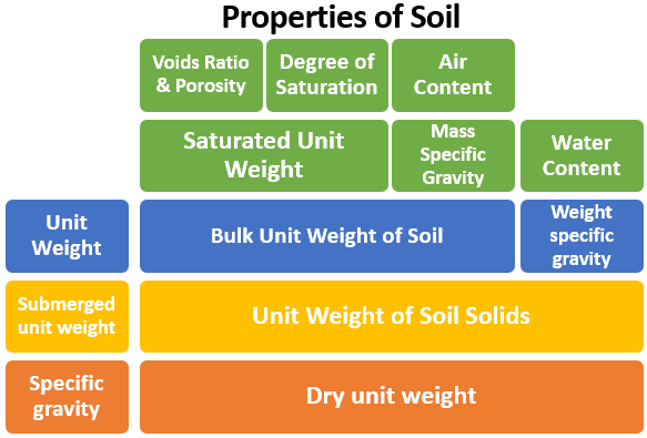
        1. Voids Ratio & Porosity

        It is defined as “The ratio of the volume of voids to the volume of soil solid”. It is denoted by “e”.

        Mathematically
        Void ratio = (Volume of Voids/Volume of Soil Solids)
        \gamma

    1.  

    2. Using volumes is not very convenient in most calculations. An alternative measure that is used is the voids ratio, e. This is defined as the ratio of the volume of voids, Vv to the volume of solids, Vs, that is A related quantity is the porosity, n, which is defined as ratio of the volume of voids to the total volume.


      Porosity

      It is defined as “The ratio of the volume of voids to the total volume of soil sample". It is denoted by “n”
      Properties and Characteristics of Soil


      Mathematically
      Porosity = (Volume of Voids/Volume of Soil Sample)
      \gamma

      2. Degree of Saturation

      It is the ratio of the Volume of Water to the Volume of Voids. It is denoted by “S”
      Mathematically
      Degree of Saturation = (Volume of Water / Volume Voids)

      \gamma

      It is expressed in percentage and is also known as Percent Saturation. In a fully saturated sample;
      Vw = Vv
      Hence S = 1 or 100%
      In case of dry sample Vw = 0, thus
      S = 0
      The degree of saturation, S, has an important influence on the soil behavior. It is defined as the ratio of the volume of water to the volume of voids.

      3. Air content:

      It is the ratio of Volume of Air to the Volume of Voids present in the given soil sample
      Mathematically
      Air Content = (Volume of Air/Volume of Voids)

      \gamma

      Void Ratio, Porosity, Degree of Saturation and Air Content are Volume Ratio.

      4. Water content:

      It is defined as “The ratio of the weight of water to the weight of solids”
      Mathematically
      Water Content =(Weight of Water /Weight of Solids)
      It is denoted by w

      w=\frac{W_{w}}{W_{d}}*100

      As a single quantity it is expressed in percentage. In Relationships or Formulae, it is expressed in fraction .
      The moisture content, m, is a very useful quantity because it is simple to measure. It is defined as the ratio of the weight of water to the weight of solid material. The water content (also known as moisture content) test is probably the most common and simplest type of laboratory test. This test can be performed on disturbed or undisturbed soil specimens.

      The water content test consists of determining the mass of the wet soil specimen and then drying the soil in an oven overnight (12 to 16 hr) at a temperature of 110 °C (ASTM D 2216-92, 1998). The water content (w) of a soil is defined as the mass of water in the soil (Mw) divided by the dry mass of the soil (Ms), expressed as a percentage (i.e., w _ 100 Mw/Ms). Values of water content (w) can vary from essentially 0% up to 1200%. A water content of 0% indicates a dry soil. An example of a dry soil would be near-surface rubble, gravel, or clean sand located in a hot and dry climate. Soil having the highest water content is organic soil, such as fibrous peat, which has been reported to have water content as high as 1200%.

      5. Unit weight:

      Several unit weights are used in Soil Mechanics. These are the bulk, saturated, dry, and submerged unit weights. The bulk unit weight is simply defined as the weight per unit volume. It is defined as “the weight of soil per unit volume of soil”.
      Mathematically
      Unit Weight of Soil= (Weight of Soil /Volume of Soil)
      It is denoted by “ γ ”

      \gamma
      It is expressed in \gamma

      6. Bulk Unit Weight of Soil:

      It is sometimes called Unit Weight only. It is the ratio of the total weight of soil to the total volume of soil.
      Mathematically
      Bulk Unit Weight of Soil = (Weight of Soil/ Total Volume of Soil)
      Unit Weight of Soil Solids
      It is also called Moist Unit Weight. The weight of the aggregate that fills a 1-cubic-foot container. This term is used because the volume contains both aggregate and voids air spaces.

      The total unit weight (also known as the wet unit weight) should only be obtained from undisturbed soil specimens, such as those extruded from Shelby tubes or on undisturbed block samples obtained from test pits and trenches. The first step in the laboratory testing is to determine the wet density, defined as _t _ M/V, where M _ total mass of the soil, which is the sum of the mass of water (Mw) and mass of solids (Ms), and V _ total volume of the soil

      7. Unit Weight of Soil Solids

      It is defined as “the weight of soil solid per unit total volume of soil solid”
      Mathematically
      Unit Weight of Soil Solid = ( Weight of Soil Solids/Volume of Soil)
      Unit Weight of Soil Solids

      8. Dry unit weight

      It is defined as “ the weight of soil solids per unit total volume of sample”

      Mathematically
      Dry Unit Weight of Soil = ( Weight of Soil Solids/Total Volume of Soil)
      Saturated Unit Weight Formula
      Since
      W = Wa + Ww + Ws = 0 + 0 + Ws = Ws = Wd , therefore,
      Saturated Unit Weight Formula
      When all the voids of soil are filled with air it is called Dry Soil and Unit Weight as Dry Unit Weight e.g. Oven Dried Soil in Laboratory
      Saturated Unit Weight Formula

      9. Saturated unit weight

      It is defined as “the total weight of saturated soil sample per units its total volume”
      Mathematically
      When all the voids of soil are filled with water it is called Saturated Soil and its weight as Saturated Unit Weight
      Saturated Unit Weight Formula

      10. Submerged unit weight

      It is defined as “the submerge weight of soil per unit its total volume”
      Mathematically
      Submerged Unit Weight = (Submerged Weight of Soil/ Total Volume of Soil)
      Saturated Unit Weight Formula
      According to the Archimedes’ Principle;
      An object immersed in water will experience a buoyant force in upward direction causing reduction in weight. Thus soil submerged in water will thus have a unit weight.
      Saturated Unit Weight Formula

      11. Specific gravity:

      It is defined as “the ratio of the unit weight of soil sample to the unit weight of water at standard temperature and pressure i.e. 4°C and 1 atm or 101.325 kPa
      OR
      It is defined as “the ratio of the density of soil sample to the density of water at standard temperature and pressure i.e. 4°C and 1 atm or 101.325 kPa
      Mathematically
      Specific Gravity = (Unit weight of Soil/Unit Weight of Water)
      Saturated Unit Weight Formula
      It is denoted by G or S.G.

      The specific gravity (G) is a dimensionless parameter that is defined as the density of solids (_s) divided by the density of water (_w), or G _ _s / _w. The density of solids (_s) is defined as the mass of solids (Ms) divided by the volume of solids (Vs). The density of water (_w) is equal to 1 g/cm3 (or 1 Mg/m3) and 62.4 pcf. For soil, the specific gravity is obtained by measuring the dry mass of the soil and then using a pycnometer to obtain the volume of the soil.
      Because quartz is the most abundant type of soil mineral, the specific gravity for inorganic soil is often assumed to be 2.65. For clays, the specific gravity is often assumed to be 2.70 because common clay particles, such as montmorillonite and illite, have slightly higher specific gravity value.

      12. Mass specific gravity

      13. Weight specific gravity

      Three Phase System of Soil

      A soil mass is a three phase system consisting of solid particles (soil grains), water and air. Thus four cases arises
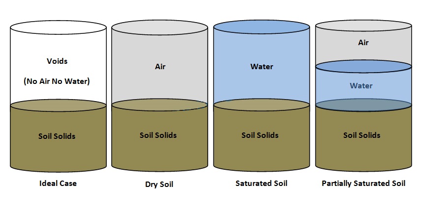
      1. Soil Particles with NO AIR and NO WATER in voids (Ideal Case i.e. 100% Compacted Soil)
      2. Soil Particles with ONLY AIR in voids (Dry Soil)
      3. Soil Particles with ONLY WATER in voids (Saturated Soil)
      4. Soil Particles with BOTH AIR and WATER in voids (Partially Saturated Soil)
      3 Phases System of Soil


  • Methods of bearing capacity determination

    Methods of bearing capacity determination


    • Analytic method i.e. through bearing capacity equations like using Terzaghi equation, Meyerhof equation, Hansen equation etc
    • Correlation with field test data e.g. Standard penetration test (SPT), Cone penetration test (CPT) etc
    • On site determination of bearing capacity e.g Plate load test, Pile load test
    • Presumptive bearing capacity (recommended bearing capacity, in various codes)
    Following are the methods:
    1. Analytical Method of Bearing capacity determination

      Analytical Method

      Lower Bound Failure

      Lower bound failure states that “If an equilibrium distribution of stress can be found which balances the applied load and nowhere violates the yield criterion, the soil mass will not fail or will just be at a point of failure i.e. it will be a lower bound estimate of capacity. Consider the equilibrium conditions in soil under the footing load. When the foundation pushes into the ground, stress block 1 has principal stresses, as shown. The push into the ground however, displaces the soil on the right side of the line OY laterally, resulting in the major principal stress on block 2 being horizontal as shown. When the two blocks are adjacent to each other at the vertical line OY, then
      Some Formulae

      Upper Bound theorem

      Upper bound theorem states that “If a solution is kinematically admissible and simultaneously satisfies equilibrium failure must result” i.e. it will be an upper bound estimate of capacity. For a possible upper bound, consider failure surface as semicircle. Taking moment about O

      Terzaghi’s bearing capacity equation (1943)

      Terzaghi developed a general formula for ultimate bearing capacity of spread footing foundation under the following assumptions:
      • The depth of the footing is less than or equal to its width (D, B)
      • The foundation is rigid and has a rough bottom
      • The soil beneath the foundation is homogeneous semi-infinite mass
      • Strip foundation with a horizontal base and level ground surface under vertical loads.
      • The general shear mode of failure governs and no consolidation if the soil occurs (settlement is due only to shearing and lateral movements of the soil)
      • The shear strength of the soil is described by s = c + σ tan

    Methods of Determining Stresses In Soil Mass

    Methods of Determining Stresses In Soil Mass


    Stress in Soil Mass

    Both immediate and consolidation settlement analysis requires estimate of increase in pressure (ΔHσ) in the soil layers from the applied loads. Several methods are available to estimate the increase in pressure at any depth z from the applied load. We will discuss:
    1. 2:1 Slope method
    2. Boussinesq Method.

    2h: 1v Slope Method

    An early method is to use 2 (horizontal): 1 (vertical) slope as shown in figure. For rectangular footing (B x L), the vertical pressure increase ΔHσ(z) at a depth z beneath the loaded area due to base load P is:
    For square footing the above equation simplifies to


    The 2:1 method compares reasonably well with more theoretical methods from z1 = B to about z2 = 4B but should not be used in the depth zone from z = 0 to B. The average stress increase in a stratum from H = Z2 – Z1 is

    Boussinesq Method:

    This method is based on theory of elasticity and is basically developed for a semi-infinite, isotropic, homogeneous half-space, however the method is used for all type of masses (layered etc), Newmark presented numerical solution to the Boussinesq equation, which is applicable beneath the corner of an area B x L.
    Δσ = q0 m Iα
    Where m is the number of corners contributing to is Δσ; m = 1 when Δσ under the corner of a footing is required and m=4 if Δσ under the center of a footing is required.


    Pile Driving Equipment - Pile Hammers

    Pile Driving Equipment - Pile Hammers

    Pile Driving Equipment:

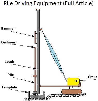
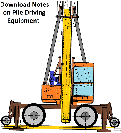
    Piles are installed by a special pile driving device known as a pile hammer. The hammer may be suspended from the boom of a crawler crane, supported on a large frame called a pile driver or carried on a barge for construction in water.
    In all cases, the hammer is guided between two parallel steel members called leads. The leads may be adjusted at various angles for driving vertical and batter piles.

    Types of Hammer:

    Several types of hammers are in use and each of which are different sizes. The hammer types are:

    1. Drop hammer:

    The drop hammer in the Pile Driving Equipmentpile driving equipment consists of a heavy ram in between the leads. The ram is lifted up to a certain height and released to drop on the pile. This type is slow and therefore not in common use. It is used in the cases where only a small number of piles are driven.
    2. Single acting hammer:

    In a single acting hammer a heavy ram is lifted up by steam or compressed air but dropped by its own weight. The energy of a single acting hammer is equal to the weight of the ram times the height of fall.

    3. Double-acting hammer:

    The double-acting hammer employs steam or air for lifting the ram and for accelerating the downward stroke. The energy of a double-acting hammer is equal to the (weight of the ram I mean effective pressure I the effective area of ram) 1 times the height of fall.

    4. Diesel hammer:

    Download Pile Driver NotesThe diesel hammer is a small, light weight and highly mobile. They use gasoline for fuel. To start the operation, the ram is raised, and the fuel is injected. As the ram is released, the ram falls and compresses air and fuel. The air and fuel becomes hot because of the compression and the air-fuel mixture is ignited. The resulting explosion
    1. Advances the pile and
    2. Lifts the ram. If the pile advance is very great as in soft soils, the ram is not lifted by the explosion sufficiently to ignite the air-fuel mixture on the next cycic, requiring that the ram be again manually lifted.

    5. Vibratory hammer:


    The principle of the vibratory driver is two counter-rotating eccentric weights. The driving unit vibrates at high frequency and provides two vertical impulses, one up and one down. The downward pulse acts with the pile weight to increase the apparent gravity force. These hummers have reduced driving vibrations, reduced noise, and great speed of penetration.

    Hammer Selection:

    Generally the size of hammer is more important factor than type of hammer. A heavy pile should be driven by a heavy hammer delivering large energy. Preferably the weight of HKjmcr should beat ^H HB1 the total weight of the pile and the deriving energy should be at Hpiie foot-pound for each pound of pile weight. Each type of hammer has its use under suitable conditions, The advantages and disadvantages of cach type are summarized below:

    Single-acting hammer :

    They arc advantageous when driving heavy piles in compact or hard soils; the heavy ram striking at - tow velocity produces least damage due to impact. The disadvantages arc low driving speed and large headroom requirement.

    Double-acting hammer:

    They are generally used to drive piles of light or moderate weight in soils of average resistance against driving. This type of hammer can drive piles at fast speed, requires less headroom and can be used to extract piles by turning them [i.e. the double-acting hammer] upside down.

    Diesel hammer:

    They are similar in application as double-acting hammers, but driving may become difficult in extremely soft ground.

    Vibratory hammer:

    They have fairly good results in silty and clayey deposits. They are used in heavy clays or soils with appreciable numbers of boulders. See above for other advantages.
    Hammer Type
    Efficiency (ɳh)
    Single and double acting hammer0.7 - 0.85
    Diesel hammers0.8 - 0.9
    Drop hammers0.7 - 0.9

    Soil Settlement Types, Calculations & Analysis - Settlement Limits

    Soil Settlement Types, Calculations & Analysis - Settlement Limits

    General:


    A soil shear failure can result in excessive building distortion and even collapse. Excessive settlements can result in structural damage to a building frame nuisances such as sticking doors and windows, cracks in tile and plaster, and excessive wear or equipment failure from misalignment resulting from foundation settlements.
    It is necessary to investigate both base shear resistance (ultimate bearing capacity) and settlements for any structure. In many cases settlement criteria will control the allowable bearing capacity.
    Except for occasional happy coincidences, soil settlement computations are only best estimates of the deformation to expect when a load is applied.

    A small computed AH of 10mm, where the measured value is 5 or 20 mm, has a large error, but most practical structures can tolerate either the predicted or measured values. What we do not want is an estimate of 25 mm and a subsequent settlement of 100 mm.
    Two Major Problems with soil settlement analysis are:
    • Obtaining reliable values of the “elastic” parameters
    • Obtaining a reliable stress profile from the applied load.

    Components of Settlement:


    The components of settlement of a foundation are:
    1. Immediate settlement
    2. Consolidation Settlement, and
    3. Secondary compression (creep)


      ΔH = ΔHi + U ΔHc + ΔHs
      ΔH = total settlement, ΔHc = consolidation settlement, ΔH = secondary compression, U = average degree of consolidation. Generally, the final settlement of a foundation is of interest and U is considered equal to 1 (i.e. 100% consolidation)

    1. Immediate Settlement

      • Immediate settlement takes place as the load is applied or within a time period of about 7 days.
      • Predominates in cohesion less soils and unsaturated clay
      • Immediate settlement analysis are used for all fine-grained soils including silts and clays with a degree of saturation < 90% and for all coarse grained soils with large co-efficient of permeability (say above 10.2 m/s)

    2. Consolidation Settlement (ΔHc)

        • Consolidation settlements are time dependent and take months to years to develop. The leaning tower of Pisa in Italy has been undergoing consolidation settlement for over 700 years. The lean is caused by consolidation settlement being greater on one side. This, however, is an extreme case. The principal settlements for most projects occur in 3 to 10 years.
        • Dominates in saturated/nearly saturated fine grained soils where consolidation theory applies.
          Here we are interested to estimate both consolidation settlement and how long a time it will take or most of the settlement to occur.

    3. Secondary Settlement/Creep (ΔHc)

        • Occurs under constant effective stress due to continuous rearrangement of clay particles into a more stable configuration.
        • Predominates in highly plastic clays and organic clays.


    Immediate Settlement Calculations

    Immediate settlement computation

        • Formula
          Where q0 = intensity of contact pressure in units of Es (Undrained Modulus of Elasticity)
          B’ = least lateral dimension of contributing base area in units of ΔHi
          Es, μ = Elastic Soil Parameters. A major problem is of course to obtain correct stress-strain modulus Es. Es can be found from laboratory tests like unconfined compression tests,
          Triaxial compression tests, and in-situ tests like SPT, CPT, Plate load tests, Pressure meter etc
          m = number of corners contributing to settlement ΔHi. At the footing center m= 4; and at a corner m = 1, at a side m = 2.
          IF = Embedment reduction factor, which suggests that the settlement is reduced when it is placed at some depth in the ground. For surface footing IF = I
          Is = Influence Factor
          Formula
          The above equation for Is is strictly applicable to flexible bases on the half space. In practice, most foundations are flexible because even every thick footing deflects when loaded by superstructure load. If the base is rigid, reduce Is factor by about 7%. The half space may consist of either cohesion less material or any water content, or unsaturated cohesive soils.

    Secondary compression/creep

      • After primary consolidation the soil structure continues to adjust to the load for some additional time. This settlement is termed secondary consolidation/secondary compression. At the end of secondary consolidation the soil has reached a new Ko-state (at-rest state).
        Secondary consolidation may be the larger component if settlement in some soils, particularly in soils with a large organic component. Secondary consolidation is associated with both immediate & consolidation type settlements, although it is usually not of much significance with immediate settlements. The magnitude of secondary compression for a given time is generally greater for NCC than for OCC.
        The rate of secondary compression Jin the consolidation (oedometer) test can be defined by the slope Cα of the final part of the compression/log time curve. Where Hsl=thickness of the laboratory sample at time t1, ΔHsl = Change in sample thickness of soil sample between t1 and t2.
        To find secondary consolidation settlement in the field (ΔHs),


        H = Thickness of the field consolidating stratum at the end of primary consolidation. Commonly initial thickness is used unless the primary consolidation is very large. Say more than 10% of initial thickness.
        t100 (f) = time taken for primary consolidation to complete in the field
        Δt = time interval beyond t100(f)
        t2 = t100 (f) + Δt = time for which secondary settlement is to be calculated.
        To find t100 (f) following relationship is used


        Where t100 (lab) and t100 (f) = time taken for primary consolidation to complete in the laboratory df, dlab = are respectively maximum drainage paths in the field and laboratory. For one-way drainage d= thickness of the layer of interest or sample thickness in the laboratory, for two-way drainage d = half of the thickness of the layer of interest/sample.

        Total settlement is the magnitude of downward movement. Differential settlement is non-uniform settlement. It is "the difference of settlement between various locations of the structure. Angular distortion between two points under a structure is equal, to the differential settlement between the points divided by the distance between them.
        Theoretically speaking, no damage will be done to a structure if it settles uniformly as a whole regardless of how large the settlement may be. The only damage would be to the connections of the underground utility lines. However, when the settlement is non-uniform (differential), as is always the case, damage may be caused to the structure.
        The tolerable, settlements of different structures, vary considerably. Simple-span frames can take considerably greater distortion than rigid frames. A fixed-end arch would suffer greatly if the abutments settle or rotate. For road embankments, storage silos and tanks a settlement of 300mm - 600mm may be acceptable, but for machine foundations the settlement may be limited to 5mm 30mm. Different types of construction materials can withstand different degrees of distortion. For example, sheet metal wall panels do not show distress as readily as brick masonry.
        To reduce differential settlement, the designer may limit the total settlement and use the following equation for the calculation of the differential settlement:
        (ΔHdiff) max = ½ ΔHtotal
        Guidelines to limiting values are suggested by a number of sources, but following routine limits appear to be conventionally acceptable (Skempton and Mac Donald, 1956)

    Sands

    1. Maximum total settlement = 40 mm for isolated footings = 40 to 65 mm for rafts
    2. Maximum differential settlement between adjacent columns = 25 mm

    Clays

    1. Maximum total settlement = 65 mm for isolated footings = 65 to 100 mm for rafts
      Maximum differential settlement between adjacent columns = 40 mm.
      The differential settlement may also be evaluated in terms of the angular distortion given by: (ΔHdiff) = Δ/L
      Where Δ = relative settlement between the two points and L = Horizontal distance between the two points. Based on a large number of settlement observations and performance of structures, the suggested limits for tolerable differential settlements are show in table below.

    2. Angular distortionType of limit and structure
      1/150Structure damage of general buildings expected
      1/250Tilting of high rigid buildings may be visible
      1/300Cracking in panel walls expected
      Difficulties with overhead cranes
      1/500Limit for buildings in which cracking is not permissible
      1/600Overstressing of structural frames with diagonals
      1/750Difficulty with machinery sensitive to settlement

    How to Write a Soil Investigation Report

    How to Write a Soil Investigation Report

    Soil Investigation Report

    Soils reports, also called “geotechnical soils reports” are prepared by a licensed geotechnical engineer or a registered civil engineer experienced in soils engineering. A soils report may be required depending on the type of structure, loads and location of the structure. The report gives understanding of earth conditions affecting a building. They are required in areas with expansive or low strength soils. Other times a soils report may be required include buildings where the foundation will be supported by fill, projects on steep slopes or where a lot of grading will be done, locations with high ground water may also require a soil investigation report prior to construction activities.

    Soils reports are obtained before construction begins. The engineer who designs the foundation uses the soils report in determining what kind of foundation design to use. In this way, problems such as differential settling over time can be avoided. There are various methods used to test soil in preparing a report. These include drilling core samples, driving steel rods into the soil to determine density and the presence of rock, test pits and the use of a seismograph.

    Soil Investigation Report

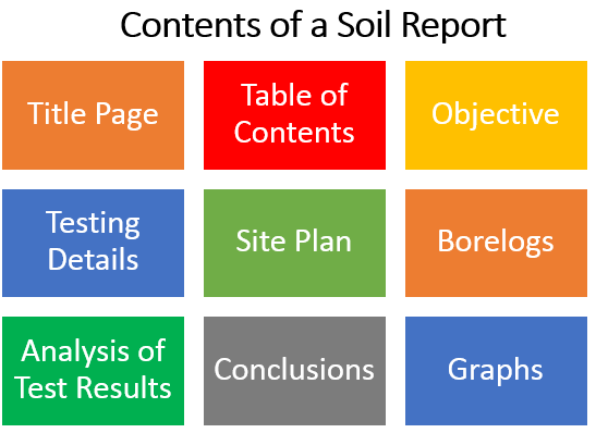
    1. Title page

    The title page of the report includes the name of the company, its address, principle investigator who has worked on the report and other relevant details of the company e.g. logo. It also includes the name of the Project, location of the project and the period of work. Client name and submission dates may also be mentioned on the title page as per requirement.

    2. Table of contents

    It contains the List of chapters or sections of the report for easy going through. A separate list of graphs, figures or annexes may also be included the report.

    3. Client’s requirements

    This is the section where the requirements and objectives of the client are listed. Here, all the information required by the client from this particular investigation is described and the names of the tests needed to collect that information are listed. In short, the scope of the report is defined here, like what this report is going to achieve.

    4. Field and laboratory testing details

    In this section general information regarding the location of the site is discussed as well as what tools, techniques and methods were used in the whole process of this geotechnical investigation. The report discusses which tests were used to collect which type of information, how samples were collected, what safety or precautionary measures were taken and how the tests were conducted in the field and in the laboratory.

    The report writer can also add a summary of the results of different tests that were conducted e.g. values of sieve analysis or Atterberg’s limits of the soil samples. A table can also be provided for better presentation and understanding of the results obtained. A list of relevant field tests may include the following soil tests:
    1. Borehole drilling activity
    2. Standard penetration test
    A list of relevant laboratory tests for geotechnical investigation of soil are as follows:
    1. Determination of moisture content and bulk density
    2. Atterberg’s limits
    3. Particle size distribution by sieve analysis
    4. Unconfined compression testing
    A detailed explanation of all the results obtained through the test must be provided in this section.

    5. Site plan

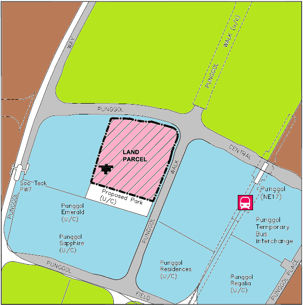
    Site plan is a sketch of the site showing all the relevant physical features around the building site, like drains, existing buildings, road, open spaces etc. The drawing should also show the location of the boreholes, if bore holes have been dug.

    Site Plan in Soil Investigation Report


    6. Bore log

    Probes for borehole logging can measure the composition of soils, map the area or provide other relevant information. Borehole logging produces an extremely detailed description of the area.  A bore log is a log that records all of the results of the borehole process. All the results of the boring process should be included here for detailed understanding of the soil profile under investigation.

    7. Analysis of test results

    This is the most important portion of the soil investigation report in which all the relevant properties of soil are discussed like nature of the soil, consistency, bearing capacity, Atterberg’s limits, specific gravity, plasticity etc. Other characteristics of the soil discussed are the factor of safety used in analysis, angle of friction, fineness modulus and soil classification of the site.

    8. Conclusions and recommendations

    In this section, the report writer suggests recommendations in the light of the results of this geotechnical investigation. The investigator recommends the number of storeys that can be built, the type of foundation, and the bearing capacity to use at the required depth. It also explains what other measures and precautions should be taken in laying of foundations, drainage and sewerage systems e.g. suggestions are shared on how to comply with the results of the tests in construction activities. In the end, the scope of the whole process and limitations of the results are also added here.

    9. Graphs

    This is the section where all the results obtained are graphed and shared with the client. These graphs may include grain size distribution curve, results of the liquid limit, plasticity chart, SPT results etc. for all types of soils encountered at the required depth at the site.


    Modes of Shear Failure of Soil - General, Local, Punching Shear Failure

    Modes of Shear Failure of Soil - General, Local, Punching Shear Failure

    Modes of shear failure

    There are three modes of shear failure, i.e. General, Local and Punching shear failures depending upon the compressibility of soil and depth of footing with respect to its breadth (i.e D/B Ratio). When the ultimate bearing capacity of the soil is reached, it may fail in one of the following three failure mode depending upon the type of soil and depth to width ratio of the footing (i.e. D/B)
    • General Shear Failure
    • Local Shear Failure
    • Punching Shear Failure

    1. General Shear Failure

    • In this mode a slight downward movement of the footing develops fully plastic zones and a sudden failure takes place with a considerable bulging of the ground surface adjacent to the footing
    • Characterized by well defined failure pattern, consisting of a wedge and slip surface and bulging (heaving) of soil surface adjacent to the footing
    • This type of failure occurs in case of dense sand or stiff cohesive soil supporting the footing
    • Failure load is well defined
    • The load-settlement diagram is similar to stress-strain for dense sand or over-consolidated clay as shown
    • The ultimate load is well defined on this curve as shown typically in figure given below
    • Sudden collapse occurs, accompanied by tilting of the footing

      • This type of failure occurs in case of dense sand or stiff cohesive soil supporting the footing
      • Failure load is well defined
      • The load-settlement diagram is similar to stress-strain for dense sand or over-consolidated clay as shown
      • The ultimate load is well defined on this curve as shown typically in figure given below

    2. Local shear failure

    • General Shear FailureFailure pattern consists of wedge and slip surface but is well defined only under the footing. Slight bulging of soil surface occurs. Tilting of footing is not expected.
      • In this mode a large deformation takes place under the footing before the development of failure zones, i.e. large vertical settlement takes place before slight bulging of the ground surface
      • Tilting of footing is not expected
      • Ultimate load is not well defined
      • It takes place in moderately compressible soils or loose sand i.e Occurs in soil of high compressibility
      • Yielding takes place close to the lower edges of the footing
      • Several yield developments may occur accompanied by settlement in a series of jerks
      • The bearing pressure at which the first yield takes place is referred to as the first-failure pressure or first failure load

    3. Punching shear failure

    • Failure pattern is not well defined
    • No bulging of ground surface and no tilting of footing occurs
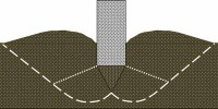
    • The yield surfaces are vertical planes immediately adjacent to the sides of the foundation
    • The ground surface may be dragged down thus, no bulging of the surface takes place
    • Failure take place immediately below footing and surrounding soil remains relatively unaffected
    • Large settlements-ultimate load is not well defined
    • Punching Shear Failure takes place in weak compressible soils with considerable vertical settlement i.e Occurs in soil of very high compressibility
    • It also occurs in the soil of low compressibility, if the foundation is located at considerable depth.
    • After the first yield the load-settlement curve will steepen slightly, but remain fairly flat
    • Punching Shear Failure may also take place in soil of low compressibility, if the foundation is located at a considerable depth


      • Modes of Shear Failure (Summary)
        General
        Local
        Punching
        Relative Settlement
        Less
        Large
        Large
        Bulging
        Significant
        Less
        No
        Tilting of Footing
        Expected
        Not expected
        Not expected
        Ultimate Load
        Well defined
        Not well defined
        Not well defined
        Failure Pattern
        Wedge +
        Slip Surface +
        Bulging
        Wedge +
        Slip Surface +
        Bulging(no or less)
        Not well defined
        Occurs in (Soil Type)
        Dense
        Less compressible
        Highly Compressible


    Bearing Capacity of Soil and Stress Analysis in Soil Mechanics

    Bearing Capacity of Soil and Stress Analysis in Soil Mechanics


    Plastic saturated soils (silts and clays) usually have lower shear strength than non-plastic cohesion less soil and are more susceptible to bearing capacity failure.
    For saturated plastic soils, the bearing capacity often has to be calculated for different conditionTotal Stress Analysis (Short term condition) that uses the un-drained shear strength of the plastic soil.
    Effective stress analysis (Long term condition that uses the drained shear strength parameters (c' & F') of the plastic soil).

    Total Stress Analysis

    Total stress analysis uses the un-drained shear strength of the plastic soil. The un-drained shear strength (sigma a) could be determined from field tests, such as the vane shear test (VST), or in the laboratory from unconfined compression tests.

    If the un-drained shear strength is approximately constant with depth, then sigma a=c and F = 0 For F = 0, the bearing capacity factors are Nc = 5.5, N ? = 0 and Nq = 1 (Put these values in Terzaghi's bearing capacity equation)
    (For strip footing)
    Q ult = 5.5c + ? Df
    Because of the use of total stress parameters the ground water table does not affect the above equation. The ultimate bearing capacity of the above example, the ultimate bearing capacity of plastic soil is often much less than the ultimate bearing capacity of cohesion less soil. This is the reason that building codes allow higher allowable bearing pressure for cohesion less soil (such as sand) than plastic soil (clay).

    Also, because the ultimate bearing capacity does not increase with footing width for saturated plastic soils, there is often no increase allowed for an increase in footing width. In some cases, it may be appropriated to use total stress parameters "c" and "F" in order to calculate the ultimate bearing capacity [For example, a structure such as an oil tank or grain elevator could be constructed and the sufficient time elapses so that the saturated plastic soil consolidates under this load. If an oil tank or grain elevator were then quickly filled, the saturated plastic soil would be subjected to an un-drained loading.]

    This condition can be modeled by performing consolidated un-drained tri-axial tests (ASTM 4767-02, 2004) in order to determine the total stress parameter (c & F). Based on F value, the bearing capacity factors would be obtained from figure; and then the ultimate bearing capacity would be calculated from equation 1. If site consists of two layers of cohesive soil having different shear strength parameters/properties; Calculate the ratio of the un-drained shear strength of layer 2 to the un-drained shear strength of layer 1 i.e.
    c2/c1 = su2/su1
    
    
    Determine the ratio T/B, where T= vertical distance from the bottom of the foundation to the top of the layer 2 and B = width of the foundation. Enter the values (c2/c1) in graph, intersect appropriate T/B curve, and determine the value of Nc For strip footing; F = 0 (N ? = 0 Nq = 1).

    Effective stress Analysis

    The effective stress analysis uses the drained shear strength (c' & F') of the plastic soil. The drained shear strength could be obtained from tri-axial compression tests. This analysis is termed as long term analysis because the shear induced pore water pressure from the loading have dissipated and the hydrostatic pore water conditions now prevail in the field. Because an effective stress analysis is being performed the location of the ground water table must be considered in the analysis.

    The first step to perform the bearing capacity analysis would be to obtain the bearing capacity factors (Nc, N ?, Nq) from Fig; using the value of F'. An adjustment to the total unit weight may be required depending on the location of the ground water table. Then Terzaghi's bearing capacity equation would be utilized (with c' substituted for c) to obtain the ultimate bearing capacity, with a factor of safety of 3 applied in order to calculate the allowable bearing capacity or pressure.

    Governing case:

    Total stress analysis will provide a lower allowable bearing capacity for soft or very soft saturated plastic soils. This is because load will consolidate the plastic soil leading to an increase in the shear strength as the time passes. For long term case, the shear strength of the plastic soil is higher with a resulting higher bearing capacity. Effective stress analysis will provide a lower allowable bearing capacity for very stiff or hard saturated plastic soils.
    Firm to stiff plastic soils are intermediate condition. The ORC and the tendency of the saturated plastic soil to consolidate (gain shear strength) will determine whether the short term condition or the long term condition provides the lower bearing capacity. Bearing capacity analysis for granular soils Granular soil does not liquefy, but rather there is a reduction in shear strength due to an increase in pore water pressure.
    Examples include sands and gravels that are below the ground water table and have a factor of safety against liquefaction is greater then 2 the earthquake induced excess pore water pressure will typically be small enough that its effect can be neglected. Using the Terzaghi's bearing capacity equation and an effective stress analysis and recognizing that sands and gravels are cohesion less (i.e. c' = 0) Terzaghi's bearing capacity equation
    Qult = cNc + q'Nq + 1/2 t BN


    For cohesion less soil
    Qult = 1/2 t BN? + t Df Nq
    
    
    For shallow foundations, it sis best to neglect the second term (?t Df Nq) in equation 2. This is because the term represents the resistance of soil located above the bottom of the footing, which may not be mobilized for punching shear failure. So, Qult = 1/2 ?t BN?
    Cohesion less soils include gravel, sands Cohesion less soil develops its shear strength as a result of frictional and interlocking resistance between the individual soil particles. This is due to confining pressure. In case of cohesion less soil c = 0
    Qult = cNc + q'Nq + 1/2 ?t BN?  First term c = 0 Qult = qNq + 1/2 ?t BN?
    For cohesion less soil the location of the ground water table can effect the ultimate bearing capacity. The depth of the bearing capacity failure is often assumed that the soil involved in the bearing capacity failure extends to a depth equal to width of footing. Thus for a ground water table located in this zone, change the third term in the above equation.